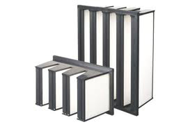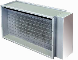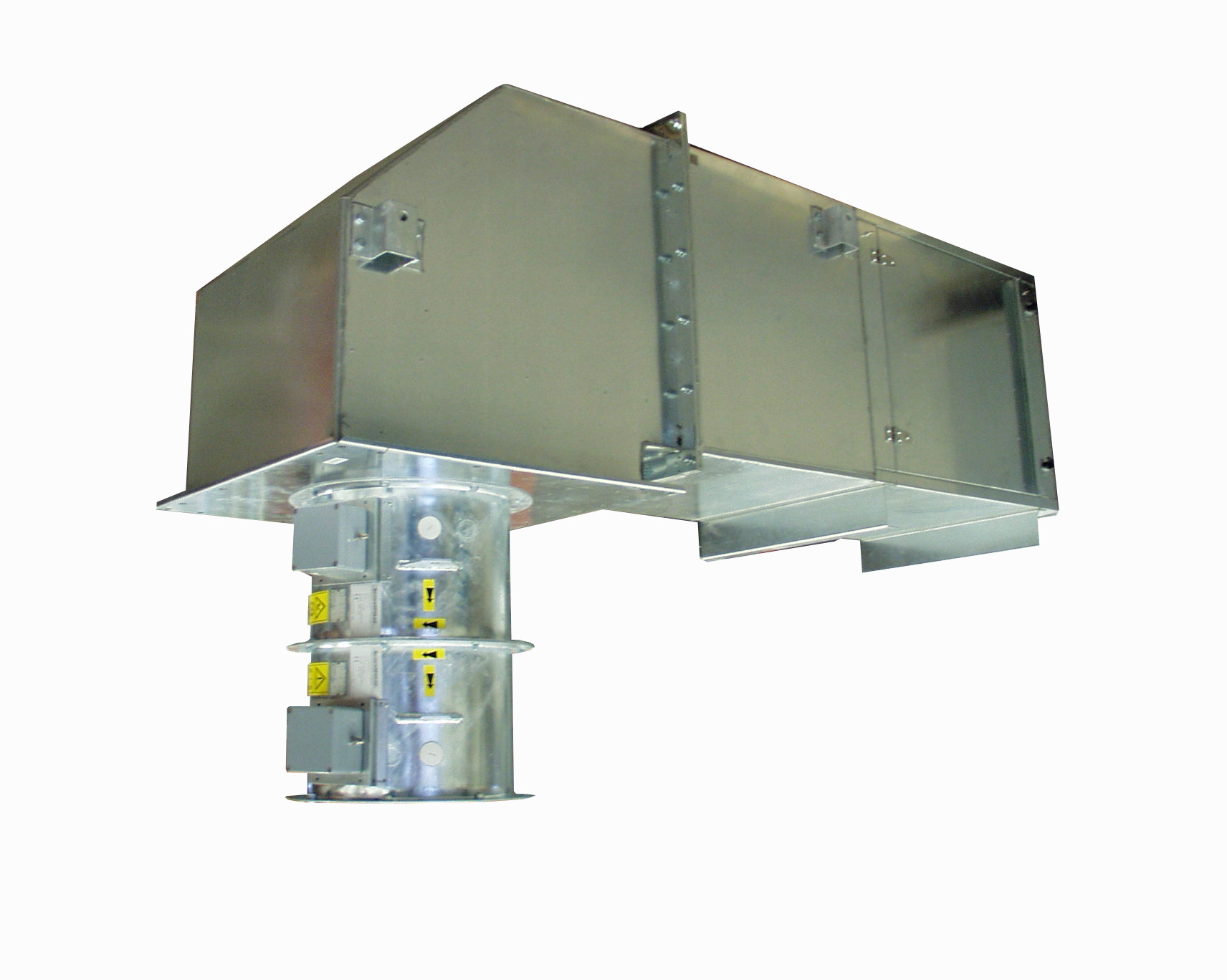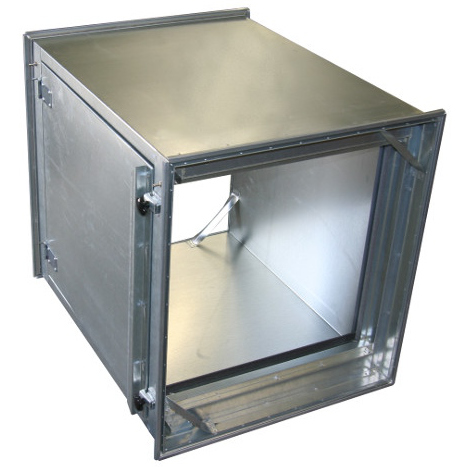
The role of droplet separators, demisters or mist eliminators is to remove a liquid from an air or gas flow using mechanical collection by surface or filaments. The liquid may be a pollutant or, like water, be per se benign, but in either case it is contaminating the air or gas.
The separation of the liquid from the air or gas within a process may:
• prevent contamination of the process
• prevent damage to, or corrosion of, downstream equipment
• recover a useful product
• prevent undesirable atmospheric emissions
The range of filter types
Liquid is entrained in an air or gas flow following either of 2 basic situations.
Demisting Units are impingement type separators consisting of multiple layers of mesh knitted from metal wire or plastic monofilaments, crimped and then assembled in successive layers. Pads fabricated in this way have a very uniform voidage with an extremely high ratio of filament surface area per unit volume of pad.
Collected liquid in the mesh forms discrete droplets on the filaments, which fall off as the force of gravity overcomes the combined forces of the rising gas and surface tension.
The high voidage achieved ensures pressure losses are correspondingly low, while removal efficiencies of droplets larger than 5 microns are essentially 100% provided the demisting unit is correctly designed for the operating conditions. The range is illustrated as in (Fig 1).
Pressure losses rarely exceed 50 mm water gauge but where pressure loss is a critical factor Demisting Units can be designed to give the highest possible collection efficiency within the operational constraints of any process
conditions. Pressure loss graph (Fig 2) demonstrates.
Units, usually with support grids, can be supplied either in one piece or in sections to pass through manways. Standard grids are of the ladder type made from 25 x 3 mm flat bar and 6 mm diameter rod in suitable material.
The primary design consideration is the velocity of the gas through the demisting unit, and the Saunders-Brown expression is a convenient means for expressing the equation for calculation of allowable vapour velocity based on liquid and gas densities
The basic equation is:
V max = K√ σL – σG
σG
Where V Max = Maximum allowable velocity
σL = Liquid density
σG = Gas density
(Expressed in similar units)
K = Constant dependent upon liquid and gas densities, viscosity and surface
tensions of the entrained liquid. For most applications the value K can be taken
as 0.105 to express V in metres/second. It is usual to design working velocities at 75% of the calculated V Max.
COALESCERS
The primary design consideration is the velocity of the gas through the demisting unit, and the Saunders-Brown expression is a convenientmeans for expressing the equation for calculation of allowable vapour velocity based on liquid and gas densities.
This unit is a pad made from composite / coknitted monofilaments and staple fibre yarn exhibiting along its length the ends of the staple fibres which compose it. These fibres are much smaller in diameter than either the yarn into which they are spun or the monofilaments – consequently forming a more efficient filter. The multitude of fibrous ends presented to the gas flow reduces the streamline effect, trapping the fine droplets within the coalescer, and any
coarse droplets so formed are re-entrained in the gas stream leaving the coalescer. They are then removed by a Demister.
The combined coalescer and fiber bed installation increases collection efficiency to > 98% in the 2-5 micron range, and fibre materials are Glass,P.T.F.E., Polypropylene and Dacron.
Pressure loss is increased but not dramatically since the BC coalescer still has a considerable free volume even allowing for the introduction of the fibrous yarn.
Typical performance figures for a 2-stage installation of a ‘BC’ Demister + ‘BC’ Coalescer are:
Efficiency
5 microns and larger – 100%
2 microns and larger – 98 – 99%
Total Pressure Loss Approx. – 1200 Pa
New Design – Single Stage
To meet market demands for similar performance in a single stage, a combination Coalescer + Demister is available in flat or coned form, depending on vessel design.
This single stage can reach efficiencies almost identical to the 2 stage system, but care must be taken when liquid load is expected to be high, as the whole of the single stage can flood, with no capacity then to remove entrained droplets downstream.

Static and carbon filters HVAC & industrial applications Dust and gas filtration

Electrical and liquid heaters HVAC & industrial applications for safe & ex areas

Vertical Vane filtration for air intakes & process water separations

Integrations for total functionality HVAC & industrial For safe & ex areas

For air and carbon filters HVAC & industrial applications Dust and gas filtration

Inovane inertial air filtration and water mist separators for your air intake solutions
To provide a good experience, we use technologies such as cookies to store and/or access device information. When you consent to these technologies, we may process data such as browsing behavior or unique identifiers on this website. If you do not consent or if you withdraw your consent, this may adversely affect certain features.